Triangulation Calculator
Estimate an observer coordinate from two known landmarks, magnetic or true bearings, declination, map scale, baseline length, and bearing uncertainty.
Triangulation estimate
| Included angle | Fix quality | Error behavior | Field note |
|---|---|---|---|
| 0-15° | Very poor | Error stretches strongly | Choose another landmark |
| 15-30° | Poor | Small bearing errors grow fast | Use as rough check only |
| 30-60° | Usable | Moderate ellipse length | Accept with wider radius |
| 60-120° | Good | Balanced intersection | Preferred two-bearing fix |
| 120-150° | Usable | Ellipse begins to lengthen | Confirm with map features |
| 150-180° | Poor | Lines nearly oppose | Add a third bearing |
| Range to landmark | 1° bearing error | 2° bearing error | 3° bearing error |
|---|---|---|---|
| 500 ft / 150 m | 9 ft / 3 m | 17 ft / 5 m | 26 ft / 8 m |
| 1,000 ft / 300 m | 17 ft / 5 m | 35 ft / 11 m | 52 ft / 16 m |
| 2,000 ft / 610 m | 35 ft / 11 m | 70 ft / 21 m | 105 ft / 32 m |
| 0.5 mi / 800 m | 46 ft / 14 m | 92 ft / 28 m | 138 ft / 42 m |
| 1 mi / 1.6 km | 92 ft / 28 m | 184 ft / 56 m | 276 ft / 84 m |
| 2 mi / 3.2 km | 184 ft / 56 m | 369 ft / 112 m | 553 ft / 169 m |
| Map scale | 0.5 mm on map | 1 mm on map | Common use |
|---|---|---|---|
| 1:10,000 | 16 ft / 5 m | 33 ft / 10 m | Detailed park map |
| 1:24,000 | 39 ft / 12 m | 79 ft / 24 m | USGS topo map |
| 1:25,000 | 41 ft / 13 m | 82 ft / 25 m | Outdoor topo map |
| 1:50,000 | 82 ft / 25 m | 164 ft / 50 m | Regional trail map |
| 1:100,000 | 164 ft / 50 m | 328 ft / 100 m | Broad road atlas |
| 1:250,000 | 410 ft / 125 m | 820 ft / 250 m | Overview planning |
| Scenario | Landmark spacing | Target angle | Starting error |
|---|---|---|---|
| Campground loop | 400-900 ft | 70-110° | 20-60 ft |
| Forest trail junction | 0.2-0.8 mi | 60-120° | 40-120 ft |
| Ridge overlook | 1-3 mi | 50-100° | 100-300 ft |
| Lake shoreline | 0.5-2 mi | 45-120° | 80-250 ft |
| Desert campsite | 1-5 mi | 60-130° | 150-500 ft |
| Whiteout travel | 0.1-0.5 mi | 80-100° | 30-150 ft |
Triangulation are a method that people use to find a position on a map when a person cannot see an exact location. To use triangulation, a person must find two known landmark and take the bearing to each of those landmarks. The location where those two bearings cross is the location of the person taking the bearings.
The fewer number of lines that are drawn from those known landmarks, the location will be more narrow; the location of the person is only that one point where the line cross. The bearings that a person measures with a compass are magnetic bearings. However, you can convert those magnetic bearings to true bearings (which are the bearings that are plotted on maps) by using declination, the difference between magnetic north and true north.
How to Find Your Location Using Triangulation
The difference between magnetic north and true north can be a few degree. If magnetic bearings are not corrected to true bearings before they are plotted on a map, the intersection point will be located many feet from the true location of the person taking the bearings. The triangulation calculator handle declination; it will automatically ask the user whether the bearings are magnetic or true bearings.
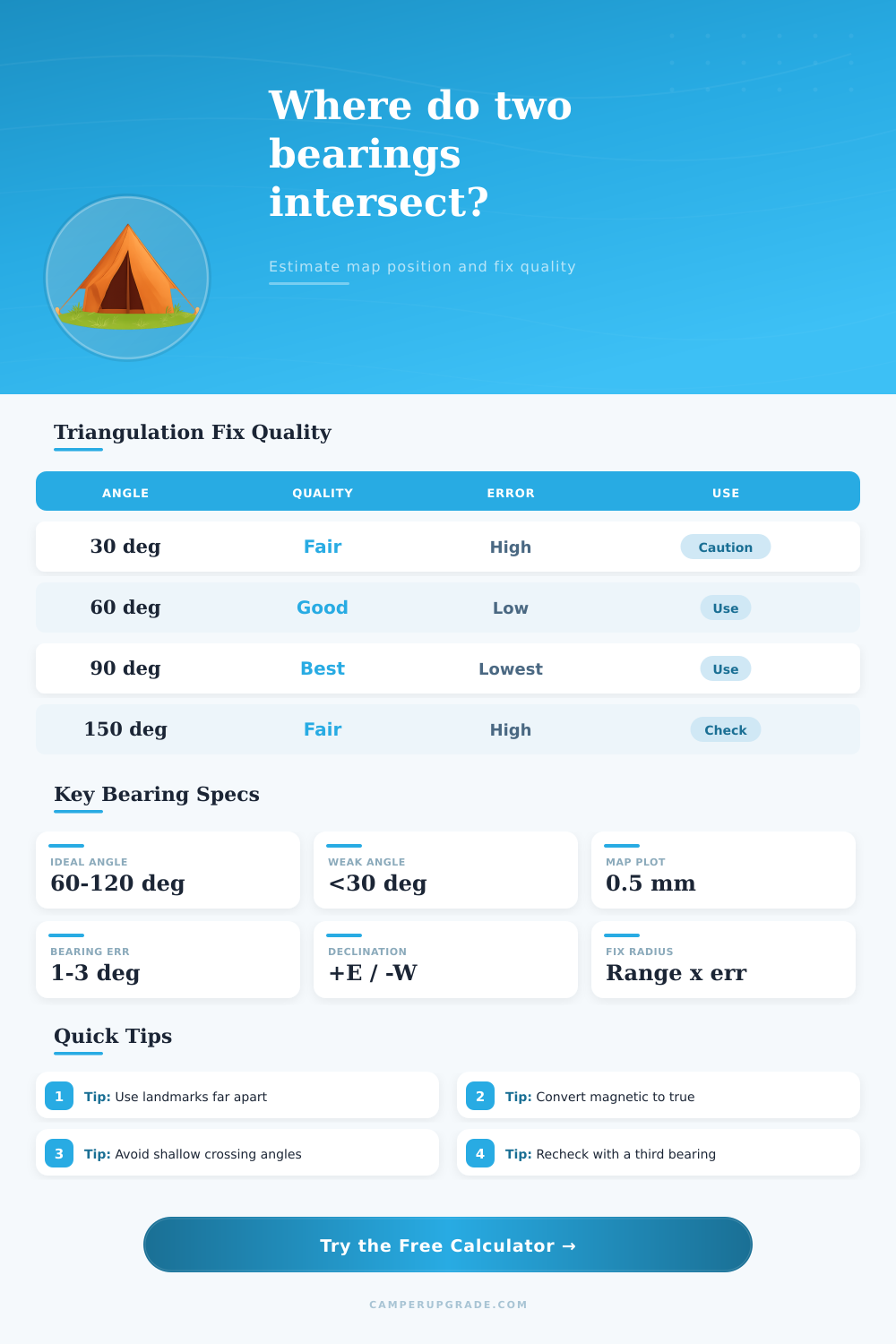
The angle at which the two lines cross will determine how small error in the bearings of those lines will impact the position of the user. If the angle between the two lines is near 90 degrees, any inaccuracy in the bearings will not impact the plotted position of the user. However, if the angle between the two lines is much more smaller than 90 degrees, any inaccuracies in the bearings will plot the user into a narrow zone of possible locations.
Similarly, if the angle between the two lines is close to 180 degrees, the inaccuracies in the bearings will also plot the user into a large zone of possible locations. The calculator includes a reference table to allow the user to determine whether the angle between the two lines will provide a useful plotted location for the user. The distance from the user to the two landmarks will also impact how inaccuracies in the bearings of those lines impact the location of the user.
An inaccuracy of 1 degree in the bearing of a line at a distance of 500 feet will only move the plotted position of the user by a few paces. However, an inaccuracy of 1 degree in the bearing of a line at a distance of 2 miles will move the plotted position of the user by more than 100 feet. The calculator accounts for both uncertainty in the bearings and the distance to the landmarks.
The radius of the calculated location is the size of the area that the user should search for there actual location. The scale of the map that is used to plot the position will also impact the uncertainty of the plotted position. On a 1:24,000 topographic map, a line that is drawn with a pencil is approximately 40 feet in length.
This line contribute to the uncertainty in the plotted position. On a smaller scale map, the same line is hundreds of feet in length. The calculator will ask for the scale denominator of the map; this value must be accounted for in the calculated radius.
In addition to the calculations that the calculator performs, there are also some factors regarding the terrain that may impact triangulation of the position of the user. Some of these factors include:
Many landmarks that are visible to the user may only be a single point on a map; in reality, though, those landmarks may be a ridge. Any inaccuracies in the bearings to a ridge will contribute to the uncertainty of the plotted position of the user.
Another factor that may impact the plotted position is local magnetic anomaly that may impact the accuracy of the compass that is being used; these anomalies may shift the bearing of the compass by a degree or two. Other inaccuracies that may impact the plotted position include tremors in the users hand and the movement of the wind. These errors may be small, but they will contribute to the uncertainty in the plotted position.
The calculator includes an “extra confidence” field for these types of errors. A third bearing to a third landmark can be taken to verify that the user is at the correct location based on the first two bearings. If the third bearing crosses close to the first plotted location, the user is likely at the correct location.
However, if the third bearing line miss the plotted location based on the first two landmarks, at least one of the original bearings is not correct or the declination value entered into the calculator was incorrect. Taking a third bearing is one of the step that many triangulation navigators take to verify that their plotted position is correct. The tool also includes presets for common types of locations.
For example, a trail junction, a lakeshore, or a ridge overlook will have preset coordinates, bearings, and scales. These presets can be used to view how the plotted position changes with the distance between the two chosen landmarks. The same two landmarks can also be selected with different values for the uncertainty of the bearings to view how the uncertainty of the plotted position changes.
Seeing how the uncertainty of the plotted position changes will allow the user to determine how careful the user must be when taking the bearings. The value of the tool is not in the plotted coordinates of the users position. The value of the tool is in the statement of the size of the area represented by those coordinates.
The coordinates represent a point, but the actual position of the user may be anywhere in the area described by the triangulation tool. The user should accept that the plotted position may not be exact. If the user accepts that the plotted position is only an area in which the user may be located, the user should search for any features within that area.
Finding any feature within that area is how the user turn a calculated location into a true location.