Fall Force Calculator
Estimate climbing fall factor, peak rope force, anchor load, and clearance need from climber mass, fall distance, rope paid out, elongation, belay slip, friction, rope type, and absorber effect.
Fall force estimate
| Fall factor | Typical feel | Common context | Planning note |
|---|---|---|---|
| 0.00-0.10 | Very light | Top-rope take or short slip | Still check swing and stretch clearance |
| 0.11-0.30 | Mild catch | Small lead slip with plenty of rope out | Belayer position often controls comfort |
| 0.31-0.70 | Moderate catch | Normal single-pitch lead fall | Manage slack and rope drag |
| 0.71-1.00 | Firm catch | Runout or low-rope fall | Expect higher force and more clearance need |
| 1.01-1.50 | Hard catch | Near-anchor or sparse protection fall | Reduce exposure before committing |
| 1.51-2.00 | Severe catch | Worst lead geometry with little rope | Avoid when possible; reassess system |
| Rope type | Dynamic elongation | Planning impact force | Use note |
|---|---|---|---|
| Single dynamic - soft | 32-38% | 7.4-8.2 kN | Longer catch, lower peak force |
| Single dynamic - balanced | 29-34% | 8.1-8.9 kN | Common all-around rope response |
| Single dynamic - stiff | 25-30% | 8.8-9.6 kN | Shorter catch, sharper feel |
| Half ropes as pair | 32-38% | 6.0-7.5 kN | Effective stretch depends on clipping pattern |
| Twin ropes as pair | 28-33% | 7.8-9.0 kN | Both strands clipped together |
| Low-stretch rope | 6-12% | 10 kN+ | Not a lead-fall rope profile |
| Static line caution | 2-6% | 12 kN+ | Use only with systems designed for it |
| Example | Inputs | Expected range | Watch item |
|---|---|---|---|
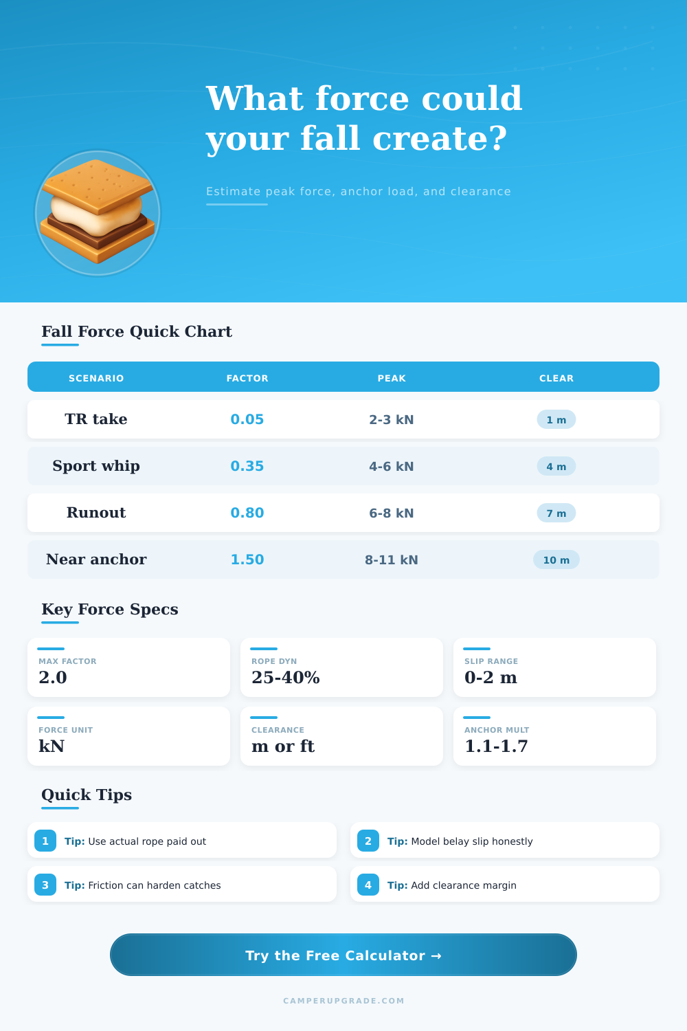
| Top-rope take | 80 kg, 0.6 m fall, 18 m rope | 2-3 kN, low factor | Swing path and rope stretch |
| Gym lead slip | 70 kg, 2.5 m fall, 14 m rope | 3-5 kN, mild factor | Clip height and soft catch |
| Sport whip | 78 kg, 6 m fall, 18 m rope | 5-7 kN, moderate factor | Rope drag and belayer stance |
| Trad runout | 75 kg, 9 m fall, 16 m rope | 6-8 kN, firm factor | Protection direction and extension |
| Low-rope fall | 82 kg, 7 m fall, 7 m rope | 8-11 kN, high factor | Ground clearance and anchor force |
| Absorber fall | 80 kg, 6 m fall, 10 m rope | Lower peak, longer catch | Clearance grows as force drops |
| System condition | Multiplier | Why it changes | Calculator use |
|---|---|---|---|
| Direct belay, low friction | 1.05-1.20 | Little pulley effect at top piece | Low friction input |
| Lead fall over top carabiner | 1.25-1.55 | Both rope legs pull on protection | Moderate friction input |
| Zigzag rope drag | 1.45-1.70 | Friction limits belay-side energy absorption | High friction input |
| Absorber in system | 0.85-1.25 | Peak force reduced by deployment | Absorber percent input |
| Static or low-stretch system | 1.40-2.00 | Very short catch distance | Static caution profile |
Fall factor is the mathematical measurement of an amount of force that will be experience by a system should the climber fall. A climber can calculate the fall factor by taking the distance of the fall and dividing it by the length of a rope that will stretch during the fall. A low factor mean that there is a long length of rope that will absorb the energy of the fall; this will result in lower peak force.
A high fall factor means that the energy of the fall is compressed into a short length of rope, which will result in high peak forces. A calculator can be used to calculate the fall factor for a given situation. There are many factor that can increase the fall factor for a climber, and that many of these factor may not be noticeable to the climber.
What Is Fall Factor and How It Affects Climbing
For instance, if a climber has sparse protection along there route, the fall factor will be increased. Additionally, if the distance between the climmer and the last point of protection is long, the fall factor will be increased. If the belayer is standing a significant distance from the wall that is being climb, this will also increase the fall factor for the climber.
Finally, the type of rope that is being used may also increase the factor. For example, if the rope is stiffer, the distance that the rope travel during the fall will be shorter. As a result, the load on the anchor point will be increased.
This value can also be enter into a calculator to determine its effect on the system. In addition to the type of rope that is used, the belay slip and the give of the harness will also impact the fall factor. If the belay has slip, or if the harness has some give when the climber lands on the ground, this will increase the distance over which the load is absorbed.
This will reduce the peak forces on the system, but will also impact the amount of clearance that should be provide for the climber beneath them. A calculator can be used to determine the effect of these variable on the system. Friction will work in an opposite manner to the stretch of the rope.
Friction will reduce the ability of the rope to stretch. For instance, if the rope is rubbing against various edge of climbing equipment, the rope will experience friction. This will lead to an increase of the forces that the climber and the anchor point experience.
A percentage for the friction that is experienced by the rope can be enter into a calculator to determine its effect on the system. Clearance is the measurement of the amount of space between the climber and the next obstacle on the route. This is determined by the fall distance, the stretch of the rope, the slip of the belay and the amount of space that should be provided for the safety of the climber beneath them.
A calculator can be used to test different assumption regarding the systems clearance. For instance, the amount of belay slip can be increased to determine the impact on the clearance variable. An absorber could also be added to the system to determine the impact on both the force and the clearance for the system.
Often, the conditions of real climbing are not the same as the conditions tested in the variables that has been tested. For instance, the effect of the wind and the temperature can have an impact upon the variables that are tested. While the tool cannot account for each of these variables, it can provide the baseline for those variables.
This baseline can be used to determine if a system is near to its limit. While the factor is often treated as a fixed value, it can change when the climber clips another piece of protection. The belayer can be moved closer to the wall, or the protection can be added at a lower point on the wall.
Using a calculator allow for the comparisons between variables to be made. For instance, each of the same masses can be tested with different length of rope to determine the impact on the system. Each of the same masses can be tested with different friction percentages to determine the impact of friction on the system.
Additionally, reference tables exist that can help to determine the impact of each of these variables on the outcome of the fall. These tables can be used to determine the impact of the type of rope that is used. Using the calculator and the reference tables will allow the climber or leader to make decision regarding where to place the protection and how much slack to allow in the system.
While the use of these tools will not eliminate uncertainty in the outcome of the fall, it will allow for those uncertainties to be measured. Thus, if the force that the fall will be create is known, the system can be adjusted prior to leaving the ground.