Carabiner Strength Calculator
Estimate applied load in kN, angle-adjusted strength, wear and gate-flutter derating, safety-factor capacity, safety margin, and orientation warning from the ratings stamped on a connector.
Carabiner strength estimate
| Marked rating | What it means | Typical range | Calculator use |
|---|---|---|---|
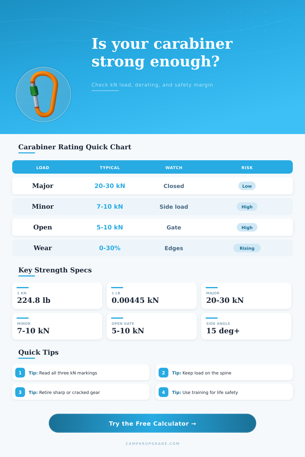
| Major axis, gate closed | Load runs lengthwise along the spine | 20-30 kN | Starting point for well-oriented loading |
| Minor axis | Load runs across the gate and spine | 7-10 kN | Target strength as angle approaches 90 degrees |
| Open gate | Gate is open, unlocked, fluttering, or pressed | 5-10 kN | Gate flutter risk blends toward this rating |
| Wear allowance | Manual derate for grooves or uncertainty | 0-30% planning | Reduces the chosen effective strength |
| Safety factor | Reserve applied after all derating | 3x-10x | Derated strength divided before margin check |
| Angle from spine | Loading condition | Strength behavior | Output warning |
|---|---|---|---|
| 0-10 degrees | Clean major-axis load | Uses most of major-axis rating | Major-axis alignment is good |
| 11-20 degrees | Slight off-axis pull | Small drift toward minor-axis rating | Monitor rotation and rope path |
| 21-45 degrees | Meaningful side loading | Derating becomes substantial | Reposition before high loading |
| 46-75 degrees | Severe cross-load tendency | Usable rating trends low | Do not treat as normal loading |
| 76-90 degrees | Near minor-axis loading | Close to minor-axis rating | Cross-loaded connector warning |
| Scenario | Factor band | What it represents | Input note |
|---|---|---|---|
| Static hanging load | 1.0-1.2x | Still load with little movement | Use only for quiet, controlled loading |
| Hammock bounce or cargo sway | 1.2-1.8x | Body movement or road vibration | Use higher end for repeated bouncing |
| Hauling start or abrupt pull | 1.5-3.0x | Short shock from slack removal | Reduce slack before loading |
| Climbing fall analysis | Varies widely | Rope, belay, fall factor, and system matter | Use formal climbing methods, not this alone |
| Unknown shock potential | 3.0x+ | Conservative planning placeholder | Do not improvise life-safety systems |
| Preset | Ratings used | Load model | Reason to compare |
|---|---|---|---|
| Locked HMS belay | 24 / 8 / 7 kN | 180 lb, 2.0x | Shows clean alignment with reserve factor |
| Ultralight wiregate | 20 / 7 / 7 kN | 35 lb, 1.6x | Gear or small camp load planning |
| Steel rescue oval | 30 / 10 / 10 kN | 250 lb, 1.2x | Higher connector rating with high safety factor |
| Hammock suspension | 24 / 8 / 7 kN | 240 lb, 1.5x | Highlights bounce and side angle sensitivity |
| Cross-load mistake | 24 / 8 / 7 kN | 180 lb, 1.5x | Shows how fast margin drops off-axis |
| Utility accessory clip | 12 / 4 / 3 kN | 30 lb, 1.3x | Clearly separates non-life-safety use |
A carabiner must hold a weight in most situations in which it is deployed. The carabiner is often the only pieces of hardware upon which a system relies. The stamped value of a carabiner only apply in specific situations.
A carabiner strength calculator will help you to understanding the actual strength of a carabiner, as the actual strength can change based on it’s use. The first factor that will change the strength of a carabiner is the angle at which the loads is applied to the hardware. Most carabiners will exhibit their highest strength values when the load is applied straight down the center of the carabiner.
How to Use a Carabiner Strength Calculator
Should the load be applied at an angle, the strength of the carabiner will decline. Carabiners that is loaded at a 20-degree angle will exhibit diminished strength compared to when they are loaded straight down their center, and at a 90 degree angle, the carabiner is at its weakest points. Carabiner strength calculators allow users to input the angle at which they intend to load the carabiner to show the expected strength of that carabiner.
The second factor that can impact the strength of a carabiners is the state of the gate. Screwgate carabiners will have their strength near it’s maximum if the gate is locked, but if the gate is not locked or is moving due to drag from the rope, the strength will diminish. The carabiner strength calculator allow users to describe the state of the gate, and the calculated value of the carabiner will reflect the strength of the carabiner.
The third factor that will impact the strength of a carabiner is the physical wear and damage on the carabiner. Any damage to a carabiner, whether it is a groove in the metal or a crack in that metal, will reduce the amount of metal that can help to support the load on the carabiner. This is not accounted for in the stamped strength of the carabiner.
Carabiner strength calculators allow users to input a percentage value for the wear on the carabiner to account for its weakened physical structure. Many people will believe that a carabiner with legible markings is still good to use, even when the carabiner is physicaly compromised. The fourth factor that a carabiner strength calculator should account for is any dynamic loading of the carabiner.
Dynamic loading is any load that is applied due to swinging or falling loads. The strength of a carabiner must be multiplied by a dynamic load factor to account for the additional strength required to counteract such scenarios. Carabiner strength calculators allow users to input this factor to account for the dynamic load on the carabiner.
The fifth factor in the calculation of the strength of a carabiner is the safety factor. After inputting the various factors that can impact the load strength on the carabiner, the value of the safety factor can be introduced. The strength is divided by the safety factor to determine how strong the carabiner should be loaded to account for potential failure.
Carabiner strength calculators use this input to provide users with the strength of the carabiner after the dynamic load is accounted for, and to alert users of whether the carabiner will pass or fail the safety factor test. If the calculated value is below one, then the carabiner system fails the safety factor test, but if the strength of the carabiner is two or three times then the dynamic load, the system passes the strength test. All of the factor should be accurately entered into the carabiner strength calculator.
If a carabiner is worn, but the user enters a wear percentage of zero, the calculated value of the carabiner will be too high. Incorrect entries for the safety factor will result in a misleadingly calculated value. Users should of run the calculation twice to ensure that the carabiner will pass under both ideal and expected conditions.
The carabiner strength calculator will not replace the physical inspection of the carabiner, but it will make visible to the user the compromises of its use.