Busbar Current Rating Calculator
Estimate RV and camper DC busbar ampacity from bar size, material, temperature rise, enclosure derating, continuous-load margin, and voltage drop.
⚡ Real Busbar Presets
🔧 Busbar Inputs
🧱 Material Conductivity Grid
📊 Busbar Reference Tables
| Nominal Copper Size | Area | Approx Open-Air Rating | Typical RV Use |
|---|---|---|---|
| 1/2 in x 1/8 in | 40 mm² | 60 to 90 A | Small branch distribution |
| 3/4 in x 1/8 in | 60 mm² | 90 to 140 A | DC panel or solar combiner |
| 1 in x 1/8 in | 81 mm² | 120 to 190 A | Battery charger or medium inverter |
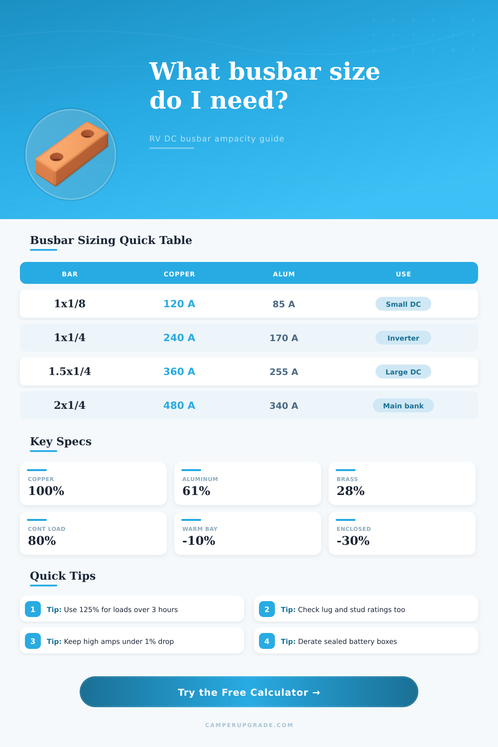
| 1 in x 1/4 in | 161 mm² | 240 to 380 A | 2000 W inverter main bus |
| 1-1/2 in x 1/4 in | 242 mm² | 360 to 570 A | 3000 W inverter or lithium bank |
| 2 in x 1/4 in | 323 mm² | 480 to 760 A | Large bank, winch, parallel inverter |
| Allowed Rise | Copper A/mm² Basis | Best Use Case | Notes |
|---|---|---|---|
| 30°C | 1.5 A/mm² | Long continuous loads | Cool touch, conservative cabinets |
| 40°C | 1.85 A/mm² | Typical RV DC gear | Good default for ventilated spaces |
| 50°C | 2.2 A/mm² | Shorter high-current runs | Verify insulation and terminal ratings |
| 65°C | 2.7 A/mm² | Equipment-rated assemblies | Use only where heat is acceptable |
| Environment | Derating Factor | Why It Matters | RV Example |
|---|---|---|---|
| Open air standoffs | 1.00 | Best convection and inspection access | Open electrical board |
| Vented cabinet | 0.90 | Reduced air movement around bar | Dinette electrical bay |
| Sealed battery box | 0.70 | Heat accumulates near cells and lugs | Under-bed battery case |
| Hot cables or cover | 0.60 | Nearby conductors and covers trap heat | Engine bay or tight inverter cover |
| Common Load | 12 V Current | Suggested Copper Area | Practical Minimum Bar |
|---|---|---|---|
| 600 W inverter | 60 A | 40 to 60 mm² | 1/2 in x 1/8 in |
| 1200 W inverter | 120 A | 80 to 100 mm² | 1 in x 1/8 in |
| 2000 W inverter | 200 A | 130 to 170 mm² | 1 in x 1/4 in |
| 3000 W inverter | 300 A | 200 to 260 mm² | 1-1/2 in x 1/4 in |
| 400 A lithium bank | 400 A | 260 to 330 mm² | 2 in x 1/4 in |
⚙ Material and Spec Comparison
💡 Busbar Sizing Tips
After three trouble free years of camping you finally leave a campsite, and when you pull off, you have an inverter trip on a light load? The breaker’s good, the battery’s good and the busbar under your dinette is hot to the touch. No, heat doesn’t go quietly. It is not failing from lack of current capacity. If it are mounted near hot cables that block airflow, or even worse, trapped in a sealed box, it may still become a bottleneck even if it looks thick enough for your amp draw.
If you have a setup involving solar, an inverter, batteries, or any sort of DC distribution in your RV, this is the calculator for you. It calculates heat, voltage drop, and ampacity on your busbars. It takes into account the size, material, airflow, and even derates based on duty cycle. It spares you from trying to guess at thermal limits. These limits change based off the environment and other coefficients. It does the math for you when you enter your own parameters, which saves you time. It makes you face the fact that a piece of copper is only as good as how well it can shed heat back to the surrounding air.
How to Choose the Right Bus Bar Size
First, you must select your materials. This sets the tone of all the rest. For example, why is copper used as a standard? It has very high conductivity, meaning that even when carrying large amounts of current there will be minimal voltage drop. In contrast, aluminum costs much less and weighs less. However, it carries much less current for its size, meaning you need a larger physical piece than you would with copper. Brass or stainless might look cool on a custom panel, but they’re horrible conductors for distributing power. You’ll invite trouble from day one if you use them for main battery feeds. The calculator accounts for these differences in conductivity, so you don’t need to memorize resistivity charts.
The shape doesn’t matter so much; it’s the size that does. You’re not just cooling the core of the bar; you also want heat to escape through the skin. More metal against the air tends to cool faster. So a wider, thinner bar will tend to cool better then a narrow, thick one. That’s why even though they look small on paper, some bars rated for one inch by a quarter inch have surprising current handling capability. The reference table on the page matches up common inverter sizes with the kind of bars that work well and lets you do a quick sanity check before diving into the nitty gritty details.
Everything depends upon the surrounding environment of the bar. The same bar will carry far more current if it is mounted on open standoffs with free airflow. This is much better than being crammed into a closed battery box under the bed. Ambient temperature rises quickly in confined areas and decreases the capacity of the bar. Mounting your electrical distribution near engine components or in a tight cabinet requires significant derating. This is the single biggest mistake DIY installers make; they purchase the correct bar only to mount it where it cannot perform properly.
The duty cycle of what you’re running will determine how cautious your sizing is. Things that operates continuously such as refrigeration units and DC-DC chargers running for hours at a time require a safety margin. They can’t be pushed to their absolute thermal limit (without risking insulation breakdown) over time. On the other hand, things that surge for only a few seconds (starting a winch or compressor motor) aren’t continuous loads but instead short surges. By specifying if you intend to run it continuously vs. Intermittently, the tool adjusts the recommendation to ensure you have enough headroom for long term operation.
While most people focus on ampacity, don’t forget about voltage drop… It’s equally important for performance. Resistance in a long path will sap some of the energy before it gets to your device. If you have too big a voltage drop, inverters may fault early or LED lights may dim too much. Keep the voltage drop to less than 1% on high current paths to protect sensitive electronics and allow for efficient power delivery. Also make sure to check your lug rating as the weakest link in the chain is what holds the whole thing together. If you’ve got a five-hundred-amp busbar then great, but all of that juice still has to get out somewhere. That means terminating onto a stud with corrosion or undersized lugs will cause the connection point to heat up well before the bar itself even starts to feel it. Using compatible materials and proper torque prevents resistance and arcing at these junctions. It is a small detail, but it makes all the difference when preventing fires.
So in the end, what size bus bar do you use? Well, it’s not as much of a number crunch based off pure power as it is a matter of how to cool it. Remember, this is going to be hauling a bunch of heavy loads through winter and summer heat waves for years on end. It has to work. Fortunately the calculator does all the math for you and gives you some easy answers to questions like “what will this handle” and “how hot will this get”. So long as you respect your duty cycles, your airflow restrictions, and your material limitations, you know your rig’s electrical system is up to the task the next time you need it. A few pieces of data and a bit of planning would of saved that poor warm busbar we started out with, and kept your lights shining bright and your campsite cozy.